Events
In UPPAAL, we declare a channel for each event, i.e., chan eventName, and represent an event by an input synchronization of the corresponding channel, i.e., eventName?. We simulate the event occurrence by an event automaton defined as follows. The event automaton only contains one state and has a self-loop synchronized by a channel output, i.e., eventName!. Fig. 1 depicts an example screen shot of the event transformation.
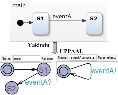
Figure 1: Event Transformation
Timer
Yakindu has two type timers: after and every. The transformation rules for both types of the timers are the same. We use the after 5s example shown in Fig. 2 to illustrate the transformation process. Similar with the event transformation, we declare a channel (chan after5s) and a clock (clock t) for the timer. The timer is represented by an input synchronization of the channel (after5s?).
We use an automaton to simulate the timer. The timer automaton only contains one state with invariant (t <= 5) to guarantee that the timer automaton is not allowed to stay in the state more than 5 time units (seconds). The timer automaton also has a self-loop guarded by t == 5, which resets the clock (t := 0) and synchronizes on the channel after5s! with the main automaton.
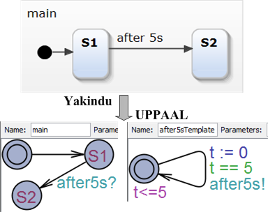
Figure 2: Timer Transformation
State
Action Yakindu has two state actions, entry and exit, which are actions carried out on entering or exiting a state. As UPPAAL does not support state actions, the entry/exit actions of a state are transformed into update of all incoming/outgoing transitions of the state.
Choice
In Yakindu, choice is a pseudo state. It divides a transition into multiple parts. To transform it to the UPPAAL model, for each incoming transition of the choice node, we combine it with each outgoing transition using AND logic, and represent a combination as a transition of corresponding states. Fig. 3 shows the screen shot of a choice transformation example.
The default trigger in Yakindu implies the lowest priority transition. As shown in Fig. 3, the transition from S1 to S3 (x == 0 && !(y == 1)) is combined by the transition from S1 to the choice node (x == 0) and the transition from the choice node to S3 (default, i.e., !(y == 1)).
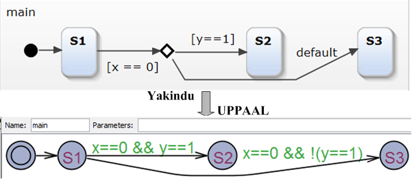
Figure 3: Choice Transformation
Transiton Priority
The Yakindu statecharts aim to model deterministic automata and avoid any transition selection randomness by enforcing transition priorities. In contrast to Yakindu, UPPAAL supports non-deterministic automata and selects transitions randomly when multiple transitions are enabled. To maintain the equivalence of the transformed model, we simulate the transition priorities in UPPAAL as follows.
Assume a state has n outgoing transitions {T1, T2, . . . , Tn} sorted in non-increasing priority order, and the guard of transition Ti is denoted as Gi, to consider transition priorities, we modify the transition guard for Ti to be Gi && !G1 && !G2 && . . . && !Gi-1.
Composite State
State Yakindu can model hierarchical automata, while UPPAAL only support flat automata. The Y2U tool needs to flat the hierarchical structure in Yakindu model, i.e., transform a composite state to a flat automaton synchronized with the original automaton. To do so, in UPPAAL, we declare two channels: active for activating/entering the composite state and deactive for deactivating/exiting the composite state. In the original automaton, we add two output synchronizations on active and deactive channels for incoming and outgoing transitions of the composite state, respectively.
The sub-automata in the composite state are separated from the original automaton. For each sub-automaton, as its all transitions have lower priorities than each outgoing transition of the composite state, we adjust the transition guards according to the above transition priority rule. Besides, we add an input synchronization on the active channel for the initial state's outgoing transition, and add a transition, which outgoes to the initial state and synchronizes on the input deactive channel, for each state except the initial one.
If a model contains nested composite states, we transform it recursively starting from the out most composite state. An example screen shot is shown in Fig. 4.
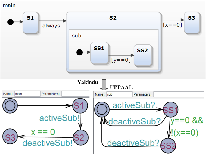
Figure 4: Composite State Transformation
String
As UPPAAL does not support string or char type, we represent a string by an integer array in which each character is encoded to its ASCII code. For example, the string "Normal" is represented by [78, 111, 114, 109, 97, 108].